Uploading Calibration Files
Calibration files are used by asset's machine control systems. They convert latitude, longitude and height values into northing, easting and elevation grid values. This calibration file can be sent wireless to the asset and also used for displaying data on VisionLink.

• Only one active calibration file can be uploaded to a site.
• To upload a calibration file, a site should have an existing site boundary or you will need to create one. Refer to Create or Modify Site Boundary to Upload Calibration File to know more.
• The calibration file may reference other files like geoid or grid datum files located in the geodata folder. If you’re planning to also upload geodata file(s), ensure the uploaded calibration file has their file name(s) referenced. Contact your survey manager to get the required site calibration and optional geodata files.
• Any VisionLink site that monitors grade productivity can have only one calibration file.
• You need to upload a calibration file if you're adding Grade or Compact assets to your site.
• The projections supported in the calibration files are:
◦ Transverse Mercator
◦ Mercator
◦ Lambert Conformal Conic 1
◦ Lambert Conformal Conic 2
◦ Oblique Sterographic
◦ Oblique Conformal Cylindrical
◦ Oblique Mercator Angle
◦ Albers Equal Area Conic
If you have any projections beyond those mentioned above, please Contact Support  .
.
To upload calibration files:
-
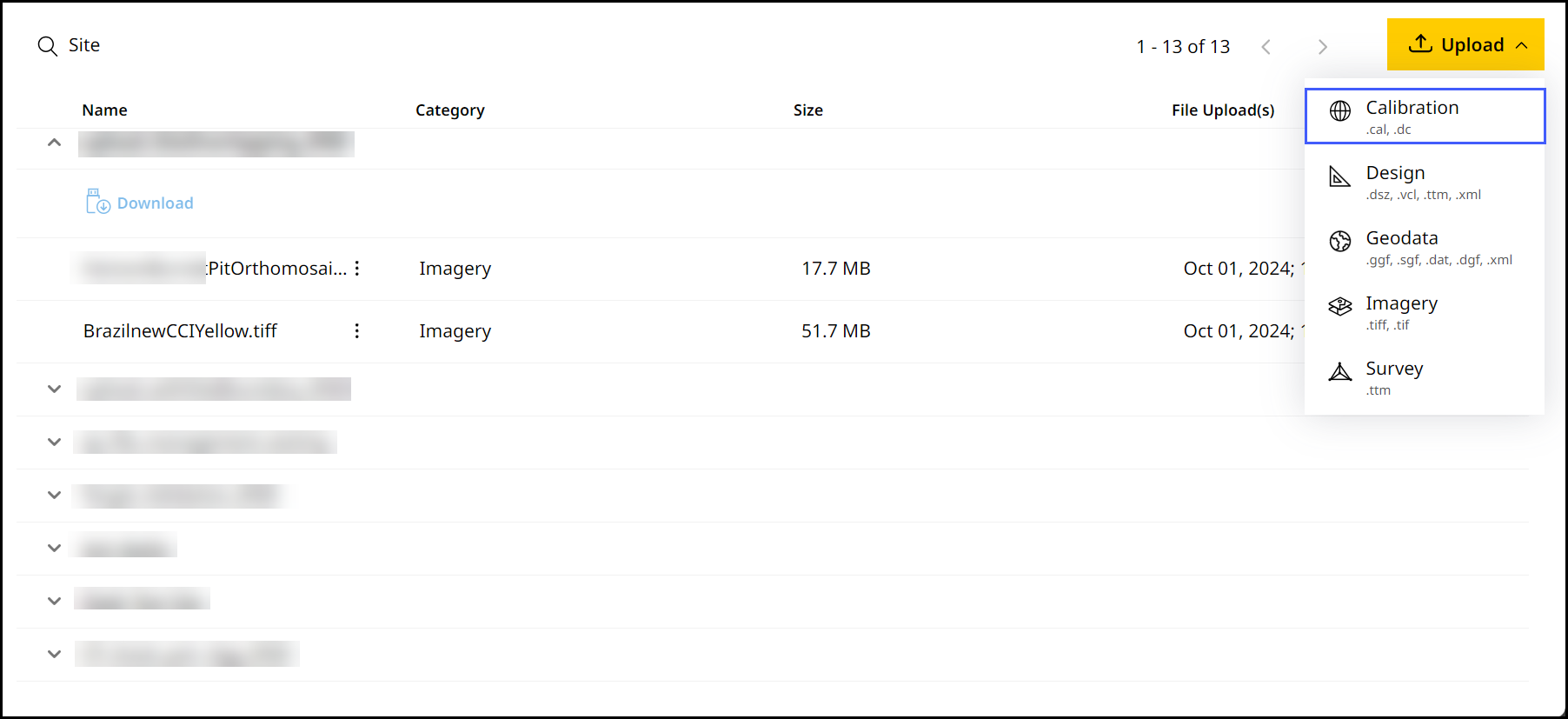
On Files, click
 > select Calibration.
-
Select Upload from the expanded menu.

-
Select the desired site from the Site Name drop down.

On the Site Name drop down, you can search for your desired site in case to quickly find and select them.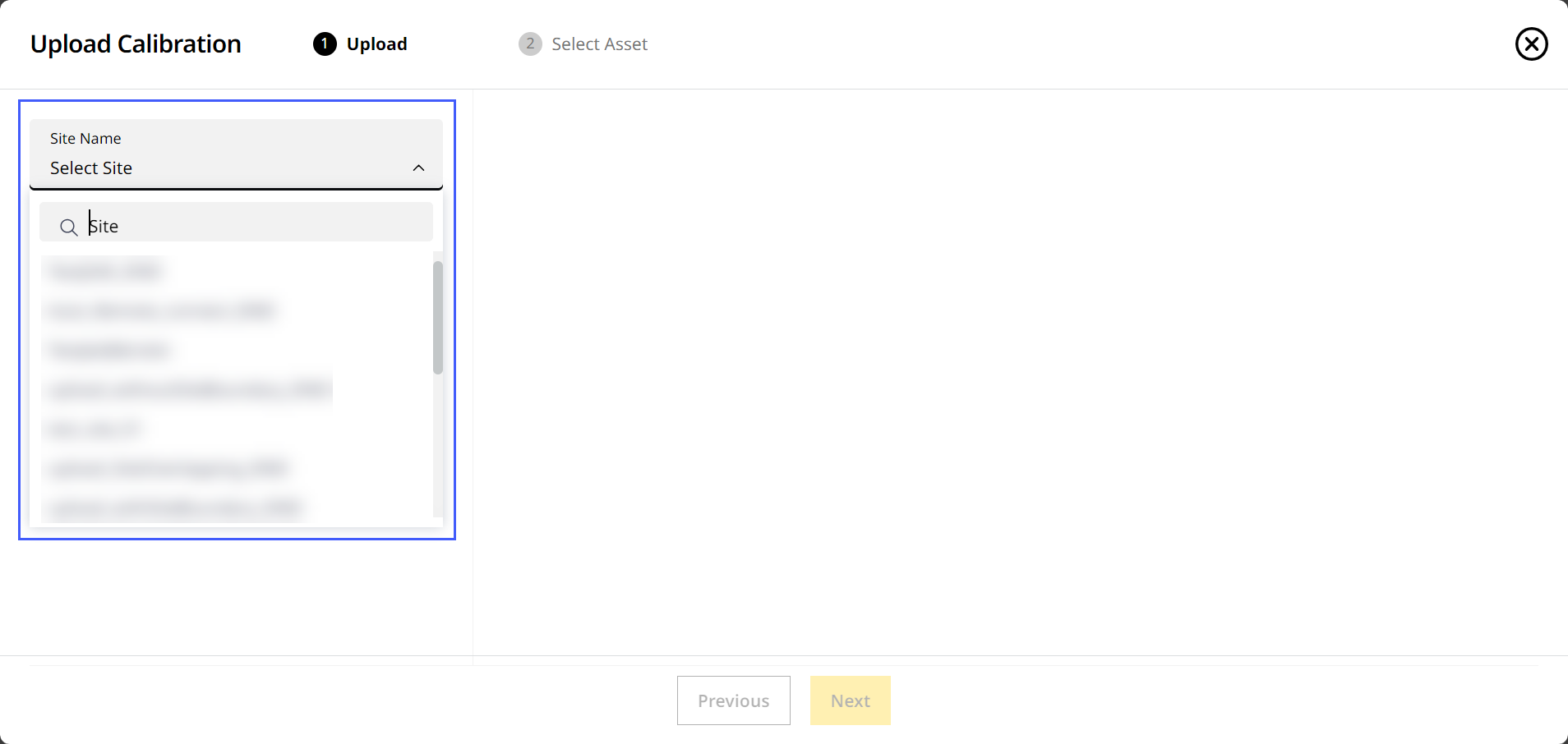
-
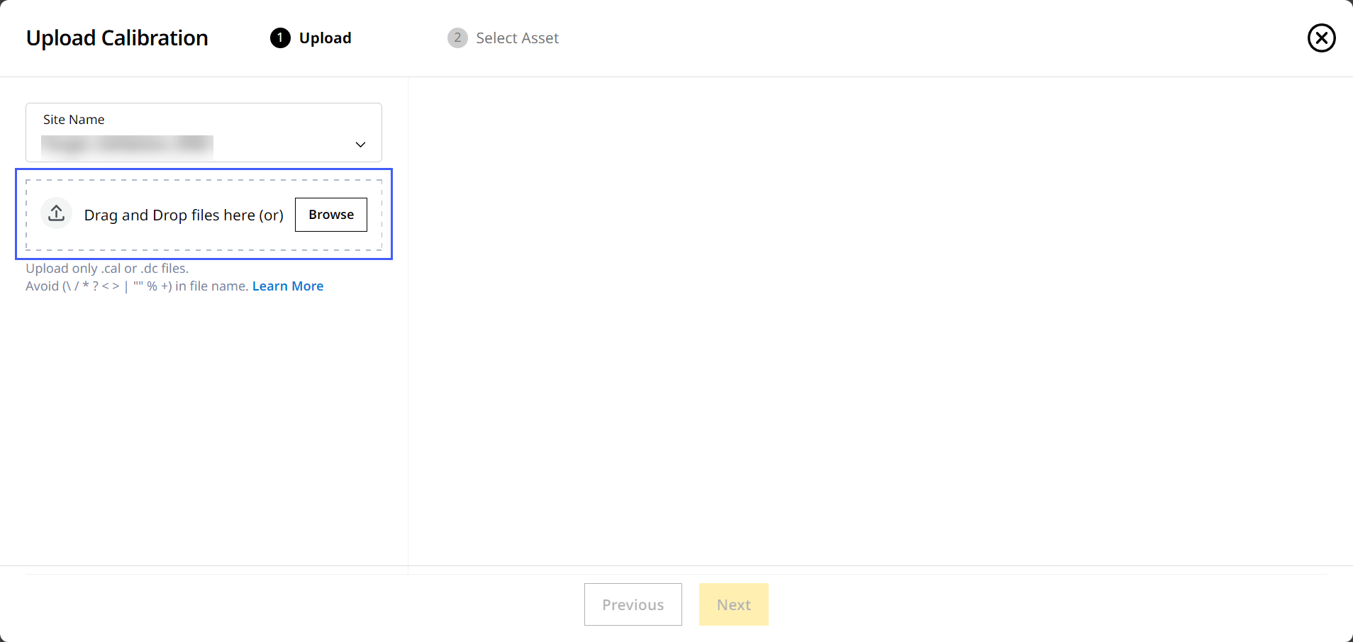
Drag and drop the file from your device or click Browse to find the file.
• On Upload Calibration, you can only upload .cal and .dc file types.
• Uploading a new calibration file replaces the previously uploaded calibration file and all associated data, including existing calibration files, surveys, design files, and geodata, which will no longer be available. After the upload, all new asset data will be processed only using the updated calibration (.cal) file.
View ImageView Image

-
If the calibration uses a geoid, the referenced geoid file (.ggf) and CoordinateSystemDatabase.xml are displayed. Keep the checkboxes selected to upload these files with the calibration. Select Upload.

-
Give it a few minutes for the upload to complete.
-
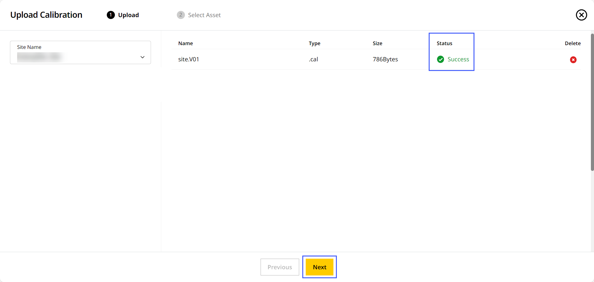
A successful upload of the file will be denoted in the Status column.
If the calibration file references a geoid file that is not available, only the calibration is uploaded. Upload the referenced file separately to ensure the calibration can be used correctly on the asset. Refer to Uploading Geodata Files to know more. -
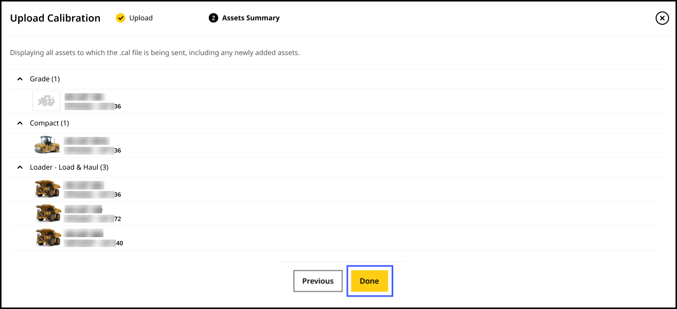
Once the process is completed, click Next to view Asset Summary. Here, you can see all assets that will receive the uploaded calibration file. Click Done.
Creating Calibration File Using Coordinate System
Create a calibration file in the application using a published coordinate system when your project requires alignment to an established geodetic reference. A list of supported coordinate systems available in the database that you can select directly while creating the calibration files. Once created, the calibration file can be sent to the assets. You can include related Grid files (Geoid.ggf ) referenced in the database when using known published coordinate system.
To create a calibration file using the coordinate system:
- Navigate to Manage > select Files > click
 .
. - Select Calibration and select Coordinate System under Create from the expanded menu.

- Select the desired site from the Site Name drop-down.
On the Site Name drop down, you can search for your desired site in case to quickly find and select them.
A new calibration file cannot be created if the file already exists for the selected site.
-
The country is automatically populated based on the site selected from the Site Name list and reflects the country associated with the site at the time of site creation.

-
Select the preferred Coordinate Zone Group from the drop down list. Based on the selected zone group, the corresponding Coordinate Zone Name options are listed. Select the zone name from the available options.

-
Once the Coordinate Zone Name is selected, a polygon representing the selected projection zone is displayed on the map. Use this polygon to visually verify that the project location is well covered within the selected coordinate zone.

-
Enable the Use Geoid File toggle to reference a geoid file for elevation adjustments. The Geoid File drop-down is prepopulated. You can keep the selected file or choose a different geoid file from the available list.
• If a geoid file is available for the selected coordinate zone, the toggle is enabled automatically.
• The Geoid File drop-down only shows options in the selected region.
-
View the map to verify the selected coordinate zone and the applied geoid file. Click Create to create the calibration file.
-
On Upload Calibration File, view the status, associated geodata files and preview the files. You can rename the file name if required.

Click Preview to view the following site calibration details.
-
After previewing the details, click Upload to send and process the calibration file.

-
Once the upload is completed, on Create & Upload .cal, view the names, types, size and status of the uploaded calibration file and the geodata file(s).

-
After the file is successfully uploaded, click Next to view all assets for which the newly uploaded calibration and the geodata files are being sent. Click Done for successful creation of calibration files.
