Body Up Switch
Switch monitoring for hauler assets helps improve the dump event accuracy for a site.
Enabling a body up switch for an asset is the result of a three-part process:
-
First, install the essential splice and wiring from the body up switch to a telematics device switch input.
-
Next, configure the switch monitoring for the asset on VisionLink.
-
Finally, once a switch is set up on VisionLink, enable the body up switch for the asset on Add Assets when creating or editing a site.
![]() Caution:
Caution:
• In case of certain haulers, their in-built software may limit the allowable gears if the body up switch input is disconnected from the main asset electronic control module (ECM).
• This in-built software works to prevent haulers from driving fast with the body up. So, verify the wiring to ensure the asset function is not limited.
Install Body Up Switch Monitoring
Refer to the owner’s manual or schematic for instructions on how to correctly install wiring for the body up switch of the specific hauler. Please note the switch you have installed as the body up switch on the asset so you can set up the same switch on VisionLink and VisionLink Productivity.

• The telematics monitoring will only work for a body up “switch” - On /Off or Open/Closed functionality.
• It will not function with body up “sensors” that provide variable, linear or angular output.
• Some examples of sensors are:
• PWM - Pulse Width Modulated
• Hz – Frequency
• IMU – Inertial Measurement Units/Accelerometers
• Potentiometer/Variable voltage
If an asset has a variable output sensor, please install an external switch to report the data through a telematics device.
For additional help, contact your local dealer or Contact Support ![]() .
.
Configure Body Up Switch on VisionLink
To configure a switch for hauler assets on VisionLink:
-
Navigate to VisionLink
 and sign in using your Admin login credentials.
 OR
ORClick on the link given in the banner in the Configure Assets step to visit VisionLink Sign In.

-
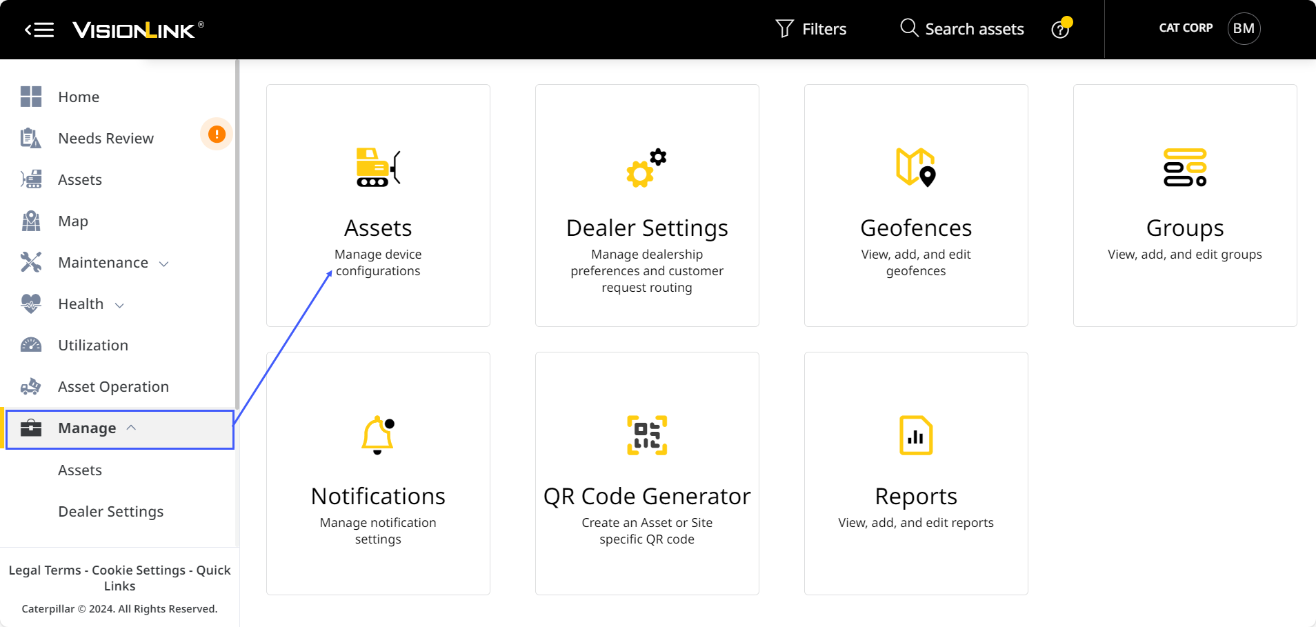
Navigate to Manage > Assets.
-
Navigate to the asset whose switch you want to configure from the list. Click more options
 > select Edit Asset Configuration.
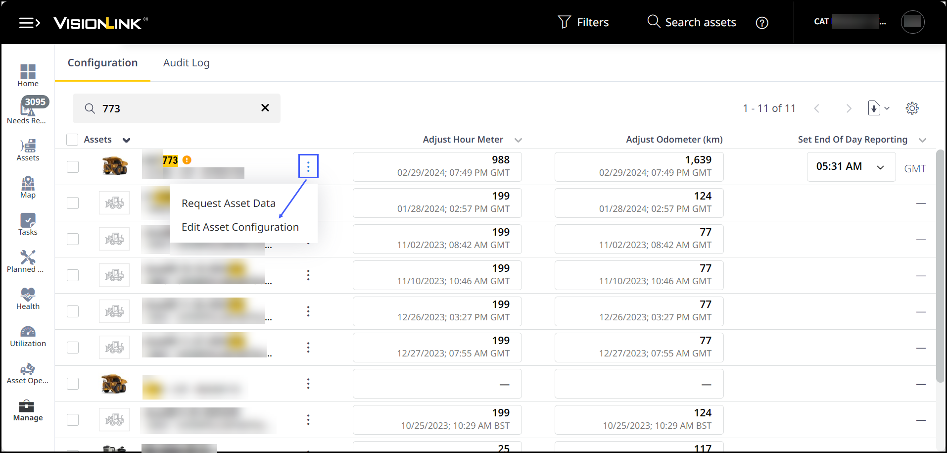

To find your asset quickly and easily, use the search options provided at the top. This narrows down the assets in the list below and highlights the search criteria as well. -
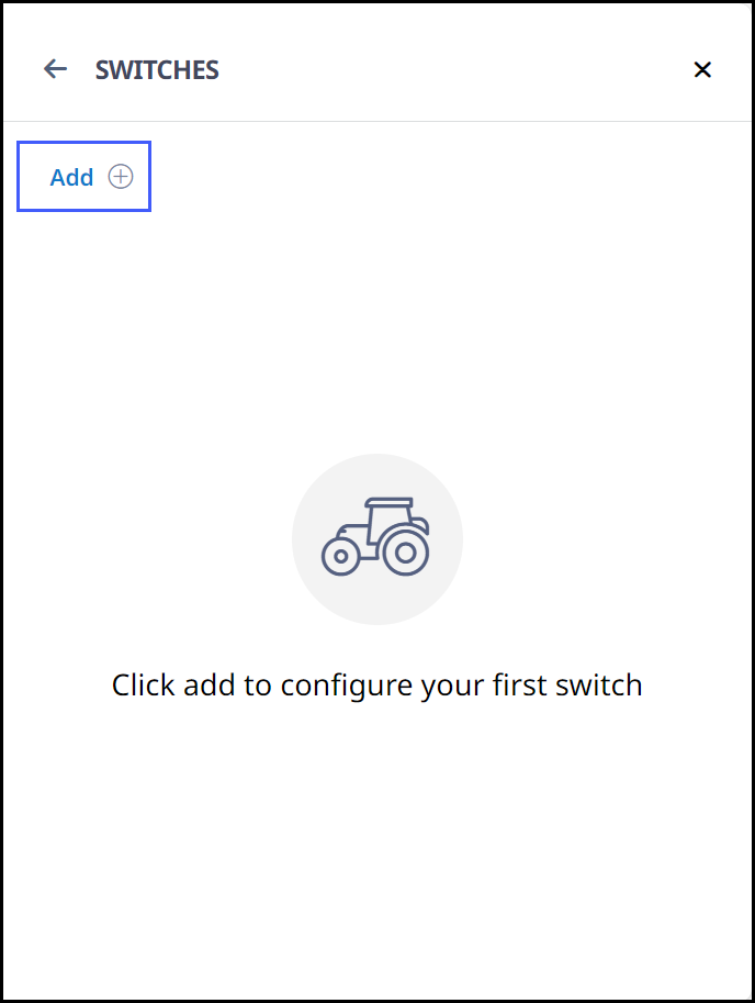
Scroll down to Configurations > select Switches.

-
Click Add + .
-
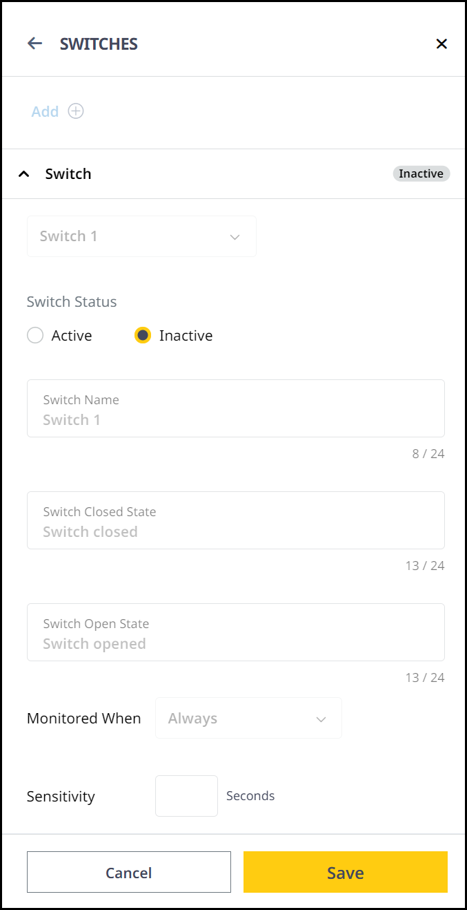
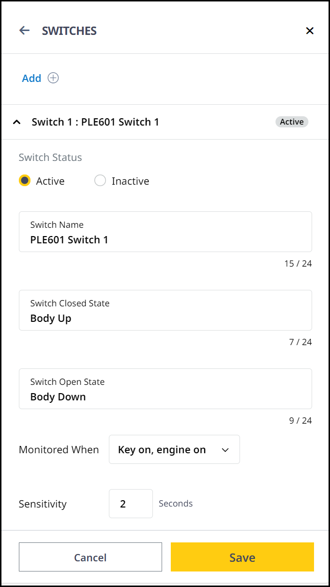
Set the configurations for the selected switch. Here, you can:
-
Select from Switch 1-4.
-
Set Switch Status to Active. This enables more options below.
-
Enter the Switch Name.
-
Specify its Switch Closed State. (max. 24 characters)
-
Specify its Switch Open State. (max. 24 characters)
-
Set when to monitor it as Key on, engine on.
-
Set the Sensitivity to 2 seconds.
• It is important to know how the switch was configured in the telematics device for installers. Configuring an incorrect switch will negatively impact the quality of the dump location data. For instance, if a seat belt switch or brake light switch is connected by mistake, instead of a body up switch.
• Switch Name should be created based on the following criteria for the system to accept them. If special characters are used for the switch name, the telematics message will not be processed properly, even if it shows as configured correctly in VisionLink.
° Maximum 24 characters.
° Upper/lower case characters from the 26 letters of the English alphabet.
° Numbers from 0 to 9.
° ASCII characters: ! " # $ % & ' ( ) * + , - . / [ \ ] ^ _ ` { | } ~ and "Space".
Table of ASCII and HEX valuesTable of ASCII and HEX values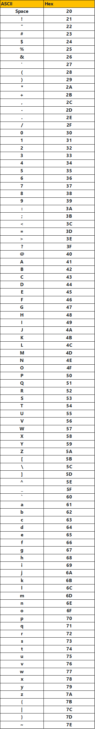
-
-
Once complete, click Save to confirm the changes.
Enable Body Up Switch in VisionLink Productivity
Note the switch you configured as body up switch on VisionLink. This will help you set up the same switch on VisionLink Productivity.
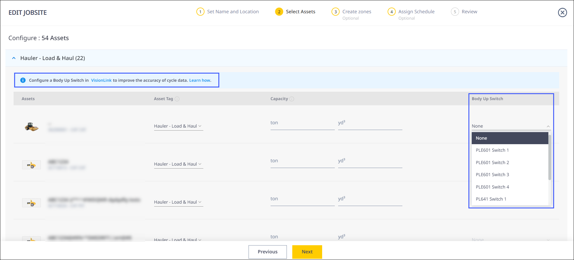
When creating or editing a site on the Add Assets step, the Body Up Switch defined on VisionLink should be selected under the Body Up Switch column.
This enables VisionLink Productivity to start utilizing the monitored switch state to clearly identify location of dump events and improve its accuracy.
• Any change occurring in the switch configuration in the asset, damage to body up switch, or monitoring wiring to telematics will not automatically reflect in VisionLink and VisionLink Productivity as a fault.
° Dump location quality may degrade to a previous lower quality with the telematics-only solution.
° Check for damaged wiring, correct switch configuration and switch status change happening on VisionLink before contacting Cat Customer Support.